29.5 TITLE OF DOCUMENT: Equipment List
PURPOSE OF DOCUMENT: Equipment list communicates to rest of engineering team, all of the equipment and package units involved in the engineering.
Equipment list is used by other departments for following purpose:
- Based on the equipment list, Planning Department prepares the detailed schedule / planning using Primavera and it is further used to monitor the progress.
- Procurement Department generates procurement status and monitors the progress of procurement on the basis of equipment list.
- Piping, mechanical, civil and electrical engineers also refer to the equipment list to understand discipline-wise responsibility of each item and monitor progress of same.
INPUTS REQUIRED (as applicable):
- Simulation report
- Block flow diagram
- Process Flow Diagrams
- Basis of Design (BOD)
CONTENTS OF DOCUMENT: It includes all major mechanical items in the plant. It is prepared unit-wise for each plant which means all equipment in a particular unit are listed together. However, it excludes electrical, instrumentation and construction equipment and all special parts (SPI).
A unique number is given to each and every mechanical item in a process plant to enable its identification.
Equipment list is one of the most effective tools extensively used and referred to during basic as well as detailed engineering phase of the project. It is used for generating field erection data sheets for process equipment.
Equipment list is made and controlled by process engineer and used by other engineering disciplines also.
Block flow diagrams & Process flow diagrams form an input for generating equipment list.
In case of package units, all equipment included within the package unit are numbered and included in equipment list with an indication of requirement of E-Motor for each item to enable a fairly correct estimation of size of MCC with respect to number of feeders.
Following are the specific contents of an Equipment List.
Please refer to Vol III Chapter 42 for template of an equipment list.
- Equipment Code : Equipment number is indicated here
- Description: Equipment title or name is indicated here
- P&ID reference number where equipment is shown
- Quantity: Numbers of equipment are indicated. (Column “a” is for number of operating equipment and Column “b” is for number of standby equipment.)
- Medium: Fluid handled by equipment is indicated
- Technical Details: Technical data for each equipment is given under this column
For example; Pumps:
Type: Centrifugal
F: Flow in m³/h
H: Differential Pressure in mlc
Heat Exchangers:
Type: Shell & Tube
Q: Heat Duty in kcal/h
A: Area in m², Length, and OD
For package units, duty parameters are given. For example; for boilers, capacity in TPH and pressure in kg/cm²g is given. Technical details of equipment within package unit are furnished only after order placement.
- Design Pressure
- Design Temperature
- Drive: Requirement of E-Motor, steam turbine, gas turbine or Electrical Heater
- Material of Construction: Broad material of construction for major parts of equipment is specified, for example;
- Pumps & Blowers – MOC for Casing & Impeller
- Heat Exchangers – MOC for shell side, MOC for tube side
- Test Pressure and Medium: For hydro test or pneumatic test
- Source of Supply: Whether the equipment is indigenous (I), foreign (F) or part of package unit (P) is indicated here.
- Group Responsibility: Different equipment is handled by different disciplines and are responsible for procurement/inquiry. In order to identify the responsible department, following codes are entered:
e.g. Process, Mechanical, Piping, Civil, Electrical, Client
Any additional information which needs to be known is specified under “Remarks” e.g. if an existing equipment is to be used, the same is highlighted. Similarly, if an equipment requires emergency power backup, this is indicated in the remarks column.
29.6 TITLE OF DOCUMENT: BLOCK FLOW DIAGRAM (BFD)
PURPOSE OF DOCUMENT: BFD is prepared in initial stage of process engineering. The purpose of block diagram in basic engineering package is to show at one place the material balance in kg/h or m³/h of all process streams entering and leaving each unit in the overall process. This communicates the overall scope of project to the rest of team.
INPUTS REQUIRED:
For the preparation of block flow diagram, the following documents are required:
- Understanding of process
- Preliminary overall General Arrangement (GA) drawing
Each unit is shown as one rectangular block and all incoming and outgoing process streams as lines with arrows. The units are also shown as per the location as per overall GA drawing.
By the above representation of unit as a block, the total process plant can be covered under one block diagram. In one block diagram, all plants in a complex can also be represented.
Similarly, an overall utility block diagram can also be generated, if required, as per contract; by showing individual utility consumption for each unit.
While selecting a capacity for utility package, block diagrams are generally prepared along with concept notes.
Refer to sample BFD attached below for an incinerator project.
29.7 TITLE OF DOCUMENT: PROCESS FLOW DIAGRAMS (PFD) and UTILITY FLOW DIAGRAM (UFD)
PURPOSE OF DOCUMENT: In a chemical process plant, raw materials go through a series of unit operations before getting converted into the finished product. Unit operations could be feed preparation, reaction, separation, distillation, filtration, crystallization, centrifugation, drying, etc.
To understand these operations easily a Process Flow Diagram (PFD) is prepared which shows the flow of chemicals/reactants through various equipment. Thus a Process Flow Diagram (PFD) shows all the important pieces of equipment with flow lines and control systems in a schematic way, along with its process description, which helps to understand the process very well.
CONTENTS OF DOCUMENTS:
A) Process flow diagram is a fundamental process drawing which depicts major process related equipment, machines, and process lines in a simple manner.
Inputs for generating process flow diagram are as follows:
– Design basis
– Simulation Report
– Thermo-physical property data
i) The contents of process flow sheets are mainly as follows:
– All equipment and machines as per simulation report
– Package units as blocks
– Equipment number (matching later with equipment list)
– Main connecting process lines between the equipment are shown. However, less important lines like minimum flow lines are not shown.
– Main control loops with control valves and impulse lines of the instruments are shown.
– Number for major open loops are shown.
– Operating pressure of the line is shown
– Operating temperature of the line is shown
– Operating pressure of the equipment is shown inside the equipment.
– Process stream numbers are marked
– Incoming lines enter from the left and leave on the right side.
– If a process stream is appearing on another sheet also then on the subsequent sheet the stream number as on the previous stream is given to identify the stream easily
ii) The minimum information of the process streams is as given below:
– Stream No.
– Composition
– Operating pressure & temperature
– Density
– Volumetric / mass flow rates
– Viscosity
– Utilities like steam, cooling water, pressurized air, etc. are shown by a line with the short code for medium
– The heat balance is given in units as per Design Basis units of measurement.
– The utility consumption is given on each consumer as volume or mass stream.
– Additional temperature and pressure data is given as required.
– Pressures is given in gauge pressure
– Flow sheets are organized to show correct relative elevations of equipment and also in relation to other flow sheets.
iii) The PFD and the material balance is the basis for the following engineering activities:
– Preparation of P&I Diagrams and to size lines.
– Preparation of list of consumption figures
– Preparation of list of emissions required by statutory bodies
– Preparation of utility summary and concept notes for utility package units
– Sizing of static and rotating equipment
– Unit equipment plot plans
– Hazid / Envid safety study
iv) Separate process flow diagrams are generated to take care of:
– Start of run conditions (SOR)
– End of run condition (EOR)
– Runaway condition
v) Also from the same process, different grades of products can be manufactured, for example, for HDPE plant:
– Extrusion grade HDPE
– Blow moulding grade HDPE
Separate PFD thus is generated for each such grade.
vi) Material balance shown in PFD is corresponding to the contractual design capacity of the plant.
vii) It is also a practice to give the heat & material balance portion in a separate A4 size sheet for large unit PFDs.
B) UTILITY FLOW DIAGRAMS:
Utility flow diagrams are prepared for each utility showing each consumer as a rectangular block. These are generated mainly for all process plant consumers.
29.12 TITLE OF DOCUMENT: PROCESS SAFEGUARDING FLOW DIAGRAMS (PSFD)
PURPOSE OF DOCUMENT: Process Safeguarding Flow Diagrams (PSFD) provide an overview of the process safeguards applied to a process plant. They show the location of pressure relieving devices based on design pressures of the system. They, therefore, serve as a starting point for the development of P&IDs.
INPUTS REQUIRED:
(i) BFD
(ii) PFD
CONTENTS OF DOCUMENT:
The following should be shown on the PSFDs:
i) Safeguarding elements:
– Ultimate safeguards (these are trip interlocks e.g. High-high, low-low):
– Relief valves will be shown along with relief destination e.g. HP or LP flare.
– Safety Instrumented Systems (SIS), if used as an ultimate safeguard.
– Capacity determining components:
- Control valves and by-passes will be shown along with action on air failure (i.e. spring action fail open/close or stay put).
- Notes should be shown as necessary to state which if any of downstream relief systems are affected by the capacity (i.e. CV) of the control valve and restriction orifices where applicable.
ii) Mitigating systems:
– All mitigating systems such as ESD valves, ROVs installed for an emergency (e.g. in pump suction lines), check valves etc.
– Emergency depressuring valves along with relief destination.
– Relevant interfaces with upstream and downstream units
Details of penultimate safeguards (i.e. alarms of high and low) do not need to be shown on PSFDs.
Process Safeguarding Flow Diagrams (PSFD) should be prepared only for new process units and repeat modified units where the changes affect the safety integrity of the system.
PSFDs are based on the initial issue of the relevant PFD. The PSFDs are intended to assist and guide the development of the P&IDs with regard to identifying safety protective devices including emergency shutdown valves, relief valves and depressuring facilities.
PSFDs should be issued before the issue of P&IDs to ensure that the required information is transposed on to the P&IDs.
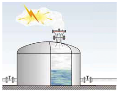
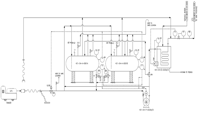
Refer sample PSFD shown below.
Fig 29.4: PSFD of a LPG bullet storage facility
Mihir’s Handbook at just USD 2.0/ebook (India: Rs.150/ebook)