6.4.1 TEMA Types
TEMA standards cover the heavy-duty heat exchangers (TEMA R) as well as the lighter duty heat exchangers (TEMA C and TEMA B). Refineries typically use only the TEMA “R” heat exchangers due to the generally severe requirements of petroleum applications; however, more moderate process services may warrant consideration of TEMA B construction.
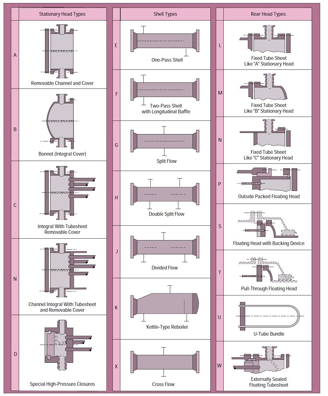
Each TEMA heat exchanger consists of following main parts: the front end stationary head (commonly referred to as “channel”); the tube bundle; the rear head and the shell. Each part can be designed in several modifications, commonly referred to as “types”.
Shown in Fig 6.17 are the TEMA standard designates which are five types of channels (A, B, C or N, and D), seven types of shells (E, F, G, H, J, K and X), and eight rear end head types (L, M, N, P, S, T, U and W). The rear end head type determines whether or not the tube bundle is removable from the shell.
i) Straight Tube, Fixed tubesheet, Type BEM, AEM, NEN, Etc.
This TEMA type is the simplest design and is constructed without packed or gasketed joints on the shell side. The tubesheet is welded to the shell and the heads are bolted to the tubesheet. On the NEN heat exchanger, the shell and the head is welded to the tubesheet. Typically, a cover plate design is provided to facilitate tube cleaning. This TEMA category, especially the NEN, is the lowest cost TEMA design per square foot of heat transfer surface.
Advantages
- Less costly than removable bundle designs
- Provides maximum amount of surface for a given shell and tube diameter
- Provides for single and multiple tube passes to assure proper velocity
- Maybe interchangeable with other manufacturers of the same TEMA type limitations
- Shell side can be cleaned only by chemical methods
- No provision to allow for differential thermal expansion must use an expansion joint on the shell side
Applications
- Oil Coolers, Liquid to Liquid, Vapor condensers, reboilers, gas coolers
- Generally, more viscous and warmer fluids flow through the shell
- Corrosive or high fouling fluids should flow inside the tubes
ii) Removable Bundle, Externally Sealed Floating tubesheet, Type AEW, BEW.
This design allows for the removal, inspection and cleaning of the shell circuit and shell interior. Special floating tubesheet prevents intermixing of fluids. In most cases, straight tube design is more economical than U-tube designs.
Advantages
- Floating tubesheet allows for differential thermal expansion between the Shell and the tube bundle.
- Shell circuit can be inspected and steam or mechanically cleaned
- The tube bundle can be repaired or replaced without disturbing shell pipe
- Less costly than TEMA type BEP or BES which has internal floating head
- Maximum surface for a given shell diameter for removable bundle design
- Tubes can be cleaned in AEW models without removing piping.
Limitations
- Fluids in both the shell and tube circuits must be nonvolatile, non-toxic
- Tube side passes limited to single or two pass design
- All tubes are attached to two tube sheets. Tubes cannot expand independently so that large thermal shock applications should be avoided
- Packing materials produce limits on design pressure and temperature
Applications
- Intercoolers and aftercoolers, the air inside the tubes
- Coolers with water inside the tubes
- Jacket water coolers or other high differential temperature duty
- Place hot side fluid through the shell with entry nearest the front end
iii) Removable Bundle, Outside Packed Head, Type BEP, AEP, etc
This design allows for the easy removal, inspection and cleaning of the shell circuit and shell interior without removing the floating head cover. Special floating tubesheet prevents intermixing of fluids. In most cases, straight tube removable design is more costly than U-tube designs.
Advantages
- Floating tubesheet allows for differential thermal expansion between the shell and the tube bundle.
- Shell circuit can be inspected and steam cleaned. If the tube bundle has a square tube pitch, tubes can be mechanically cleaned by passing a brush between rows of tubes.
- The tube bundle can be repaired or replaced without disturbing shell piping
- On AEP design, tubes can be serviced without disturbing tubeside piping
- Less costly than TEMA type BES or BET designs
- Only shell fluids are exposed to packing. Toxic or volatile fluids can be cooled in the tubeside circuit
- Provides large bundle entrance area, reducing the need for entrance domes for proper fluid distribution
Limitations
- Shell fluids limited to non volatile, non toxic materials
- Packing limits shell side design temperature and pressure
- All tubes are attached to two tubesheets. Tubes cannot expand independently so that large thermal shock applications should be avoided
- Less surface per given shell and tube diameter than AEW or BEW
Applications - Flammable or toxic liquids in the tube circuit
- Good for high fouling liquids in the tube circuit
iv) Removable Bundle, Internal Split Ring Floating Head, Type AES, BES, etc.
Ideal for applications requiring frequent tube bundle removal for inspection and cleaning. Uses straight-tube design suitable for large differential temperatures between the shell and tube fluids. More forgiving to thermal shock than AEW or BEW designs. Suitable for cooling volatile or toxic fluids.
Advantages
- Floating head design allows for differential thermal expansion between the shell and the tube bundle.
- Shell circuit can be inspected and steam cleaned. If it has a square tube layout, tubes can be mechanically cleaned
- Higher surface per given shell and tube diameter than “pull-through” designs such as AET, BET, etc.
- Provides multi-pass tube circuit arrangement.
Limitations
- Shell cover, split ring and floating head cover must be removed to remove the tube bundle, results in higher maintenance cost than pull-through
- More costly per square foot of surface than fixed tube sheet or U-tube designs
Applications
- Chemical processing applications for toxic fluids
- Special intercoolers and aftercoolers
- General industrial applications
v) Removable Bundle, Pull-Through Floating Head, Type AET, BET, etc.
Ideal for applications requiring frequent tube bundle removal for inspection and cleaning as the floating head is bolted directly to the floating tubesheet. This prevents having to remove the floating head in order to pull the tube bundle.
Advantages
- Floating head design allows for differential thermal expansion between the shell and the tube bundle.
- Shell circuit can be inspected and steam or mechanically cleaned
- Provides large bundle entrance area for proper fluid distribution
- Provides multi-pass tube circuit arrangement.
- Suitable for toxic or volatile fluid cooling
Limitations
- For a given set of conditions, this TEMA style is the most expensive design
- Less surface per given shell and tube diameter than other removable designs
Applications
- Chemical processing applications for toxic fluids
- Hydrocarbon fluid condensers
- General industrial applications requiring frequent cleaning
vi) Removable Bundle, U-Tube, Type BEU, AEU, etc.
Especially suitable for severe performance requirements with maximum thermal expansion capability. Because each tube can expand and contract independently, this design is suitable for larger thermal shock applications. While the AEM and AEW are the least expensive, U-tube bundles are still an economical TEMA design.
Advantages
- U-tube design allows for differential thermal expansion between the shell and the tube bundle as well as for individual tubes.
- Shell circuit can be inspected and steam or mechanically cleaned
- Less costly than floating head or packed floating head designs
- Provides multi-pass tube circuit arrangement.
- Capable of withstanding thermal shock applications.
- The bundle can be removed from one end for cleaning or replacement
Limitations
- Because of U-bend, tubes can be cleaned only by chemical means (although nowadays, new techniques of the fluid pressurized scraper, similar to a pipeline pig, are available)
- Because of U-tube nesting, individual tubes are difficult to replace
- No single tube pass or true countercurrent flow is possible
- Tube wall thickness at the U-bend is thinner than at the straight portion of tubes
- Draining of tube circuit is difficult when mounted with the vertical position with the head side up.
Applications
- Oil, chemical and water heating applications
- Excellent in steam to liquid applications
Mihir’s Handbook at just USD 2.0/ebook (India: Rs.150/ebook)