24.1 Flame Arresters:
Flame arresters are used:
- to stop the spread of an open fire
- to limit the spread of an explosive event that has occurred
- to protect potentially explosive mixtures from igniting
- to confine fire within an enclosed, controlled, or regulated location
- to stop the propagation of a flame traveling at sub-sonic velocities
Few of their common usages are:
- fuel storage tank vents
- fuel gas pipelines
- safety storage cabinets for paint, aerosol cans, and other flammable mixtures
- the exhaust system of internal combustion engines
- the air intake of marine inboard engines
- overproof rum and other flammable liquors
Explosive mixtures can burn in various ways. The following, among other things, can influence the combustion process: the chemical composition of the mixture, possible pressure waves, pre-compression, the geometric shape of the combustion chamber, and the flame propagation speed.
The relevant combustion processes for flame arresters are defined by international standards:
Explosion is the generic term for abrupt oxidation or decomposition reaction producing an increase in temperature, pressure or both simultaneously.
Deflagration is an explosion that propagates at subsonic velocity. Depending on the geometric shape of the combustion area, a distinction is drawn between atmospheric deflagration, pre-volume deflagration and in-line deflagration.
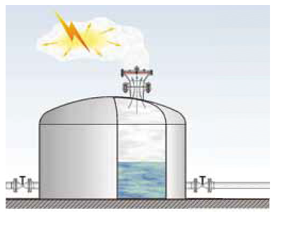
Atmospheric deflagration (Fig. 24.1.1) is an explosion that occurs in open air without a noticeable increase in pressure.
Fig 24.1.1: Atmospheric deflagration
Pre-volume deflagration (Fig. 24.1.2) is an explosion in a confined volume (such as within a vessel) initiated by an internal ignition source.
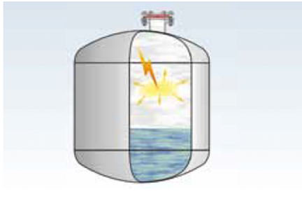
Fig 24.1.2: Pre-volume deflagration
In-line deflagration (Fig 24.1.3) is an accelerated explosion within a pipe that moves along the axis of the pipe at the flame propagation speed.
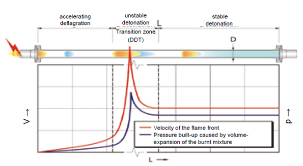
Fig 24.1.3: In-line deflagration in pipe
Stabilized burning is the even, steady burning of a flame, stabilized at or close to the flame arrester element. A distinction is drawn between short time burning (stabilized burning for a specific period) and endurance burning (stabilized burning for an unlimited period) (Fig 24.1.4).

Fig 24.1.4: Stabilised burning
Detonation is an explosion propagating at supersonic velocity and is characterized by a shock wave.
A distinction is drawn between stable detonations and unstable detonations (Fig 24.1.3). A detonation is stable when it progresses through a confined system without a significant variation of velocity and pressure characteristic (for atmospheric conditions, test mixtures and test procedures, typical velocities are between 1,600 and 2,200 meter/second). A detonation is unstable during the transition of the combustion process from a deflagration into a stable detonation. The transition occurs in a spatially limited area in which the velocity of the combustion wave is not constant and where the explosion pressure is significantly higher than in a stable detonation.
24.2 Spray nozzles:
A spray nozzle is a precision device that facilitates dispersion of liquid into a spray. Nozzles are used for three purposes: to distribute a liquid over an area, to increase liquid surface area, and create impact force on a solid surface. A wide variety of spray nozzle applications use a number of spray characteristics to describe the spray.
Spray nozzles can be categorized based on the energy input used to cause atomization, the breakup of the fluid into drops. Spray nozzles can have one or more outlets; a multiple outlet nozzle is known as a compound nozzle.
Understanding sprays, drop size, and the strengths and characteristics of nozzle types and correctly positioning them are fundamental to the desired process result.
By creating a large droplet surface area, sprays are used to generate the high rates of heat and mass transfer that is necessary in spray drying, liquid waste incineration, and spray quenching applications. Spray nozzles are applied in a wide variety of process applications with a wide range of criticality. An example is the quenching of hot gases where high performance, high reliability, and robustness are required. Another usage of nozzles is manual pressure washing of equipment. Similarly, Desuperheating of superheated steam by spraying water into the superheated steam as well as chemical injections into main streams are other usages of spray nozzles.
Types of spray nozzles are:
- Single fluid spray nozzles
- two-fluid atomizing nozzles
- rotary disk
- ultrasonic.
24.2.1 Single-fluid nozzle
Single-fluid or hydraulic spray nozzles utilize the kinetic energy of the liquid to break it up into droplets. This most widely used type of spray nozzle is more energy efficient at producing surface area than most other types. As the fluid pressure increases, the flow through the nozzle increases, and the drop size decreases. Many configurations of single fluid nozzles are used depending on the spray characteristics desired.
(i) Plain-orifice nozzle
The simplest single fluid nozzle is a plain orifice nozzle as shown in the fig 24.2.1. This nozzle often produces little if any atomization, but directs the stream of liquid. If the pressure drop is high, at least 25 bars (2,500 kPa), the material is often finely atomized, as in a diesel injector. At lower pressures, this type of nozzle is often used for tank cleaning, either as a fixed position compound spray nozzle or as a rotary nozzle.

Fig 24.2.1: Plain orifice spray nozzle
(ii) Shaped-orifice nozzle
The shaped orifice (fig 24.2.2) uses a hemispherical shaped inlet and a ‘V’ notched outlet to cause the flow to spread out on the axis of the ‘V’ notch. A flat fan spray results which is useful for many spray applications, such as spray painting.
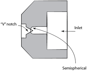
Fig 24.2.2: Flat fan spray pattern spray nozzle
(iii) Surface-impingement single-fluid nozzle
A surface impingement nozzle (fig 24.2.3) causes a stream of liquid to impinge on a surface resulting in a sheet of liquid that breaks up into drops. This flat fan spray pattern nozzle is used in many applications ranging from applying agricultural herbicides to row crop to painting.
The impingement surface can be formed in a spiral (fig 24.2.4) to yield a spiral shaped sheet approximating a full cone spray pattern or a hollow-cone spray pattern.
The spiral design generally produces a smaller drop size than pressure swirl type nozzle design, for a given pressure and flow rate. This design is clog resistant due to the large free passage.
Common applications include gas scrubbing applications (e.g., flue-gas desulfurization where the smaller droplets often offer superior performance) and fire fighting (where the mix of droplet densities allow spray penetration through strong thermal currents).
24.7 Liquid Filtration:
Liquid filtration plays a very important part in any process. Filtration is a process whereby solid particles present in a suspension are separated from the liquid or gas employing a porous medium, which retains the solids but allows the fluid to pass through. When the proportion of solids in a liquid is less, the term clarification is used. It is a common operation which is widely employed in production of sterile products, bulk drugs, and in liquid oral formulation.
The suspension to be filtered is known as slurry. The porous medium used to retain the solids is known as filter medium. The accumulated solids on the filter are referred as filter cake & the clear liquid passing through the filter is called the filtrate.
24.7.1 Types of filtration
Based on the mechanism, three types of the filtration are known.
i) Surface filtration: It is a screening action by which pores or holes of the medium prevent the passage of solids. The mechanisms, straining and impingement are responsible for surface filtration. For this purpose, plates with holes or woven sieves are used. Example is cellulose membrane filter.
ii) Depth filtration: This filtration mechanism retains particulate matter not only on the surface but also at the inside of the filter. This is aided by the mechanism entanglement. It is extensively used for clarification.
Examples are ceramic filters and sintered filters.
iii) Ultra filtration: Ultra filtration is a pressure-driven membrane transport process that has been applied, on both the laboratory and industrial scale. Ultra filtration is a separation technique of choice because labile streams of biopolymers (proteins, nucleic acids & carbohydrates) can be processed economically, even on a large scale, without the use of high temperatures, solvents, etc.
24.7.2 Filter Selection:
In choosing the filter, selection depends on several considerations which are covered by the following queries:
- What is the duty of the filter?
- What is the sizing requirement to carry the process flow rate and contain the solids removed?
- What filter area (ft2) and cake capacity (ft3) is needed?
- Is there a requirement to prefilter?
- Is the filter for a fine-filtration requirement?
- Is manual or automatic operation preferred?
- Is the process batch or continuous operation?
Manually operated filters include basket filters, plate-and-frame filter presses, plate filters and some pressure leaf filters.
Pressure-leaf type filters have features to achieve self-cleaning or automatic cake discharge. These features allow discharge of the filter cake by washing the cake off the filter medium with internal spray headers or by vibrating the cake off with a pneumatic vibrator. Sometimes pressure leaf filters are operated manually with respect to valve operation, but their self-cleaning features remove them from the manual classification. Both horizontal and vertical tank designs are available with hydraulically operated quick-opening closures to speed the opening of the tank for dry cake discharge. Filter media types used are cloth covers, felt covers and wire mesh.
(i) Basket filters
For coarse filtration, the basket or strainer filter type is selected, and consists of a pressure vessel type housing with a perforated internal member that separates the coarse solids from the process liquid. The internal element is made of perforated metal or is a coarse wire-woven basket. Refer point 24.9 for details on basket filters.
(ii) Plate-and-frame filter press
The oldest filter type is the plate-and frame filter press. These filters rely on the type of media used, which is generally the filter sheet or pad for depth filtration not requiring a precoat. The chamber between the filter plates becomes filled by the removed solids until full.
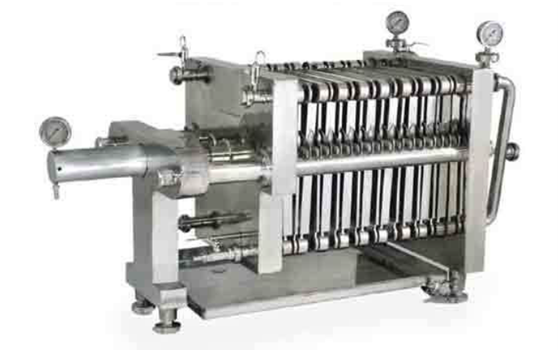
Fig 24.7.1: Plate and Frame filter
24.9.2 Basket type strainers:
These are used for services where heavy solids or filtration is necessary e.g. fuel oil service, strainers before specialized exchangers like core exchangers.
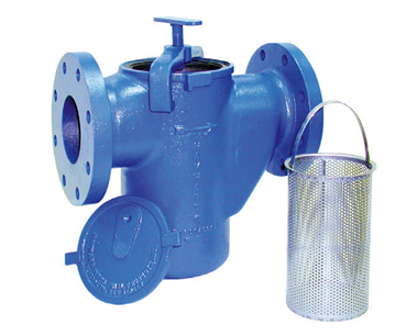
Fig 24.9.3: Simplex basket strainer
A procedure to specify area required of basket strainer is provided below:
24.9.3 Strainer Specification
Liquid Services
For liquid services to core exchangers use permanent basket line strainers (slant top style). The perforated basket shall be lined with mesh stainless steel wire liner if there is any potential for the presence of particulates in a fluid system, otherwise 40 mesh is adequate. Body materials and flange ratings will depend on the exchanger design conditions. The volume or dimensions of the basket shall be specified as follows:
Volume = (1) Volume of mill scale formed on the inside wall of the upstream pipe back to the source vessel or drum. + (2) Volume allowance of mill scale, dirt, and debris expected in the source vessel.
Use scale thickness of 1/32”.
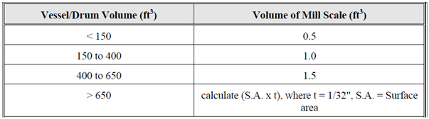
Table 24.9.1: Volume of mill scale (ft3)
This calculated volume shall be specified to be below the path of fluid flow.
Also, note that to obtain proper volume of the basket, the length may become prohibitive. For these cases, increase the body size leaving the inlet and outlet flange line sizes to obtain a more desirable basket geometry.
Vapor Services:
Use the identical procedure as for liquids, but, source vessel allowance may be neglected. (These services are typically from tower or vessel overheads where debris/scale settles out at the bottom of the vessel.)
24.9.4 Pressure Drop Calculation
– As a general thumb rule, an engineer should allow for two extra hard tees for a ‘clean’ strainer when performing preliminary pressure drop calculations. A more accurate pressure drop estimate should then be obtained through the specific strainer vendor. This back check needs to be performed to insure that the ‘hard tee’ assumption for pressure loss is conservative enough. Attached (Figs 24.9.7 to 24.9.11) are some specific pressure drop curves for reference use for detailed calculations in case vendor data is unavailable at time of detailed hydraulic calculation, as well as a pressure drop for screen clogging curve, Fig 24.9.12.
Mihir’s Handbook at just USD 2.0/ebook (India: Rs.150/ebook)