3.5 OVERALL PUMP OPTIONS:
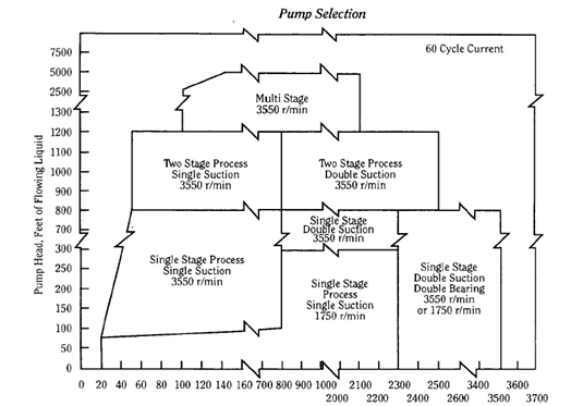
The following chart gives an introduction of pump selection options as a function of flow and required head.
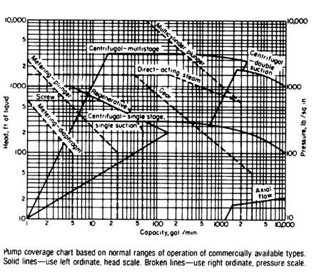
Fig 3.1: Pump Selection Guide Chart
Pump Capacity, gpm
Fig 3.2 Centrifugal pump selection chart
The specification of process pumps involves a step-by-step approach. The process engineer must select a pump with the best efficiency for the full range of process operating conditions.
The major types of pumps available are listed in the following table.
| Kinetic | Positive Displacement |
| Centrifugal: | Reciprocating: |
| 1. Radial Flow | 1. Piston |
| 2. Axial Flow | 2. Plunger |
| 3. Mixed Flow | 3. Diaphragm |
| 4. Turbine | |
| Special: | Rotary: |
| 1. Jet | 1. Gear |
| 2. Gas Lift | 2. Screw |
| 3. Hydraulic Ram | 3. Lobe |
| 4. Inertia | 4. Vane |
| 5. Progressive Cavity | 5. Flexible Chamber |
| 6. Concrete pumps | 6. Flexible Tube (peristaltic) |
Table 3.1 Types of Pumps
Comparison between centrifugal and positive displacement type is provided below in table 3.2.
| Parameter | POSITIVE DISPLACEMENT | DYNAMIC |
| Definition | Increases pressure by operating on a fixed volume in a confined space | Increases pressure by using rotary blades to increase fluid velocity |
| Types | Screw, gear, reciprocating, progressive cavity | Centrifugal, axial |
| Characteristics | i) Constant volume
ii) Variable differential head iii) Relatively insensitive to liquid properties iv) Relatively insensitive to system changes v) Not self-limiting |
i) Variable volume
ii) Constant differential head iii) Sensitive to liquid properties iv) Sensitive to system changes v) Self-limiting |
| Characteristic flow versus differential head curve | 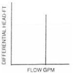 |
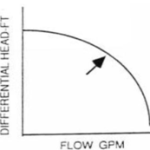 |
Table 3.2: Comparison between positive displacement and dynamic pumps
Many applications can be handled by a horizontal or vertical centrifugal pump. The following should be considered.
| Feature | Horizontal | Vertical |
| Space Requirements | Less headroom | Less floor area, more head room |
| NPSH | Requires more | Requires less |
| Flexibility for future change | Less | More |
| Maintenance | More accessible | Major work project |
Table 3.3 Horizontal & Vertical Centrifugal Pump Selection Guide
A selection table showing the physical range of head and capacity suitable for the various types of pump is provided below.
| Pump Type | Capacity m3/h (usgpm) | Head m (ft) | |
| Minimum | Maximum | ||
| Low Capacity | |||
| Peripheral | 0.23 (1) | 4.5 (20) | 213 (700) |
| Vane | TBD | 17 (75) | 122 (400) |
| Reciprocating Plunger | 0.23 (1) | 34 (150) | Over 1,525 (5,000) |
| General Use | |||
| Reciprocating Power | 4.5 (20) | 227 (1,000) | Over 305 (1,000) |
| Direct | 1.4 (5) | 114 (500) | Over 305 (1,000) |
| Centrifugal 1 – Stage | 2.7 (10) | 1820 (8,000) | Over 150 (500) |
| 2 – Stage | 2.7 (10) | 1820 (8,000) | Over 210 (700) |
| Multistage | 2.7 (10) | 680 (3,000) | Over 305 (1,000) |
| Screw | 2.7 (10) | 180 (800) | Over 305 (1,000) |
| High Capacity | |||
| Centrifugal 1 – Stage | 1.4 (5) | 11,350 (50,000) | 15 – 122 (50 – 400) |
| (Low Head) | 57 (250) | 22,700 (100,000) | 3 – 61 (10 – 200) |
| Mixed Flow | 227 (1,000) | 45,400 (200,000) | 0 – 7.5 (0 – 25) |
Table 3.4 Pump Selection Table
3.6.8 Stream Specific Gravity (Multiple Fluids)
Occasionally, pumping services will be designed to operate on fluids with widely differing gravities. When calculating the hydraulics for the different cases, the fluid with lighter gravity will often control the pump sizing. However, it should be stressed that when the pump is operating at a lower volume throughput, often at a noticeably higher differential head and incidentally lower pump efficiency, the effect of the heavier gravity fluid will give a pump discharge pressure considerably in excess of the design requirement of the lighter material. The process engineer must be aware of two potential problems during operation of the heavier gravity fluid:
- Downstream equipment (piping, heat exchangers, vessels, etc.) may be over pressurised. In this event, either equipment ratings will need to be increased or safeguarding measures must be implemented to prevent over pressurising.
- The motor may be overloaded. In this event a larger motor may be required or means of restricting flow will need to be implemented to prevent overload.
- On the data sheet, the process engineer should also note the specific gravity of the heaviest liquid that the pump is expected to handle.
Relations in Discharge of Identical Centrifugal pump handling liquids of different specific gravity is shown in below fig 3.17.
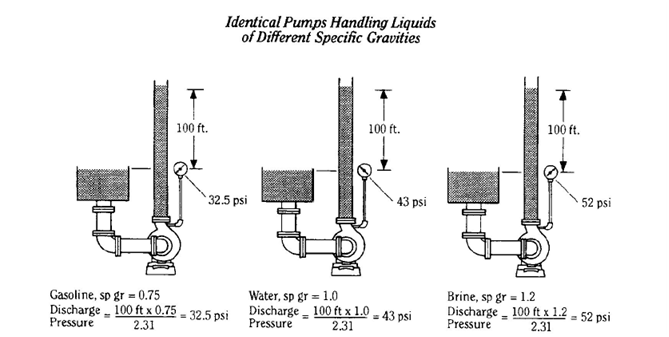
Fig 3.17: Typical performance of same centrifugal pump handling different fluids..
What this diagram implies is that e.g. if same centrifugal pump of say 20 mlc head is used to pump water (sp. gr of 1.0) and also mercury (sp. gr of 13.6), then ignoring effect of viscosity for this example and considering atmospheric suction, the discharge pressure of water will be 2 barg while of mercury will be 27.2 barg. Thus, in case of pumping mercury, if pump has been procured originally only for water, then either motor will trip due to overload or pump casing may bust if it is of lower design pressure.
3.6.18 Parallel vs. Series Centrifugal Pump Operation
3.6.18.1 Parallel Pump Operation
The combined characteristics of pumps operating in parallel is obtained by adding their individual flowrates for a given value of head.
Pumps with different pump curves should generally not operate in parallel. When this cannot be avoided, the pump with the lower shut-off head must be protected against operating at flows below the allowable minimum flow.
The shut-off head of the combined pump discharge system is determined by the pump with the highest shut-off head.
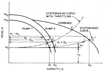
Fig 3.29: Dissimilar two centrifugal pumps in parallel operation
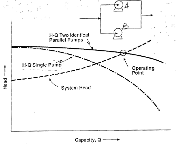
Fig 3.30: Two identical centrifugal pumps in parallel operation
Centrifugal pumps may be combined into parallel operation for numerous reasons. Some are:
- Capacity increase is required for an existing pumping service and a new pump is added in parallel to one or more existing pumps. The engineer should be aware that the system flow will not necessarily increase in proportion to the number of pumps added
- Very high reliability is required of the pumping service without total reliance on the functioning of an auto-start control mechanism. Also, the loss of one pump will not cause sudden total shutdown of the system.
In order to meet a requirement for flow capacity higher than normal on an infrequent basis, it may be preferable to have the primary pump and its spare operate in parallel, instead of designing each pump for the full above-normal flow rate.
- The required service capacity may exceed the utility energy supply available for a single driver or driver type e.g. many companies have low voltage (LV) to high voltage (HV) power supply cutoff at 160 KW motor size. Thus multiple parallel pumps may be installed to make each motor LV.
- Desire for operating flexibility in power supply or type could result in multiple pumps with different driver types e.g. one motor driven with other steam turbine driven.
- The use of multiple pumps may allow investment savings. For example, three 50%-pumps may require lower a total investment than two pumps sized for 100% for the service capacity. (This would be possible but unusual.)
For parallel operation, the head-capacity curve is obtained by adding the individual pump capacities at any one given head. Pumps with different head-capacity curves will have different flow rates. The process engineer must be certain that one pump is not “backed out” or forced to operate below its minimum flow.
When pumps are operated in parallel it is imperative that their performance curve rise steadily to shut-off. A drooping type of performance curve gives two possible points of operation and pumps may oscillate between each other and cause surging. In parallel operation additional pumps can be started up only when their shut-off heads exceed the head developed by the pumps already running. Pumps operating in parallel should have a shut-off head 10-20% higher than the rated head (API 610).
Another difficulty may occur as a result of inadequately engineered suction lines such that one pump suction steals from the other. The remedy is to design for equal suction heads and to assure that available NPSH is sufficient to satisfy each pump.
Adequate check valves must be used on pump systems operating in parallel to minimize possible back flow through pumps and to minimize the effects of surge which is possible on some parallel pumping systems.
It is advisable to provide a piping bypass system so that either pump can be operated without the other. Aside from flexibility, a bypass system permits operation at reduced conditions during maintenance, inspection or repair of either pump.
Caution: Pumps in Parallel
A problem that can occur with pumps in parallel is shown in fig 3.31. Two pumps are never exactly alike. If two pumps are installed in parallel, one pump may take more than half of the total flow and the other pump less than half. The pump with the lower flow rate may be operating below its minimum acceptable flow rate. As the fig shows, the head produced by the two pumps will be identical because they are connected to the same process. If the head produced by pump B is lower than head produced by pump A, the situation shown in the fig will occur. Pump B will decrease its flow rate until it can produce the same head as pump A.
This situation is most dangerous when one pump is driven by a motor and the other pump by a turbine. It is impossible to set the two speeds exactly equal, and the difference in speed will cause a difference in head produced.
If two pumps are nominally identical and both driven by motors, the two head curves can be assumed to be within 3% of each other. If so, one can make the worst assumption, that is, the head of pump B is 3% lower than the head of pump A. Then, using the system operating conditions, plot the flow through both pumps. Make sure that the lowest flow rate is not below the pump minimum allowable flow rate.
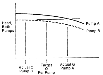
Fig 3.31: Pumps in parallel
3.6.18.2 Series Pump Operation
The combined characteristics of pumps operating in series is obtained by adding their individual heads for a given flow rate.
The shut-off head of the combined pump discharge system is determined by adding the shut-off heads of individual pumps.
Note that NPSH is generally a key design consideration for the first pump only since the first pump acts as a booster for the 2nd pump in series.
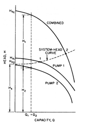
Fig 3.32: Performance curve for two dissimilar centrifugal pumps in series
Pumps may be designed to operate in series arrangement for any of the following reasons:
- The head requirement exceeds the capability of a single pump.
- The differential pressure requirement is low enough at times that one of several pumps in series can be turned off, as in transportation pipe lines.
3. The primary pump has a high NPSHR Therefore, a low-head booster pump is installed to pressure the suction of the higher-head pump.
4. Plant feed must be transferred from a remote storage area to the suction of an on-site high-head pump.
5. Two or more pumps are preferred over a multistage pump in erosive slurry operation.
For series operation, the head-capacity curve is obtained by adding the two heads at any given capacity.
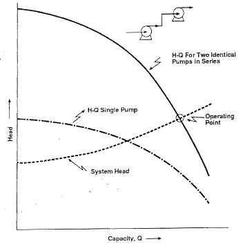
Fig 3.33: Two identical centrifugal pumps in series
It is important that adequate suction pressure be available to all pumps, especially to the first pump in series operation. If the first pump in a series system is deprived of adequate NPSH, its capacity will be reduced until NPSHR equals NPSHA. Then the capacity through all the pumps in series will be reduced, resulting in a significant overall flow loss.
The design pressure for piping and equipment, including the pumps themselves, should be carefully examined in a series-flow operation especially if the pumping system can be deadheaded.
The engineer should be aware that reliability is reduced for the series-flow service since operation is now dependent on not just one pump but each pump in the series.
Caution: Pumps in Series
Two pumps in series will generate much more discharge pressure than one pump alone. In some cases, this pressure might be greater than the design pressure of the downstream piping or other equipment. This condition must be checked before proceeding with an installation of two or more pumps in series. It is important to check the design pressure at the condition called “pump shutoff pressure.” Shutoff pressure is obtained when the downstream control valve is closed and the pumps operate at zero capacity and maximum head. The shutoff pressure is equal to the pressure in the suction vessel plus the shutoff delta P of both pumps combined. See Fig 3.34 and the example table beneath it. For this example, the normal operating discharge pressure is satisfactory because it is less than the design pressure. However, at shutoff, the discharge pressure downstream of the second pump would be greater than the equipment design pressure. This situation is not allowed. One remedy is to install a safety valve at the discharge of the second pump as shown.
View complete index of Chapter 3: Pumps
Mihir’s Handbook at just USD 2.0/ebook (India: Rs.150/ebook)