Case Scenario:
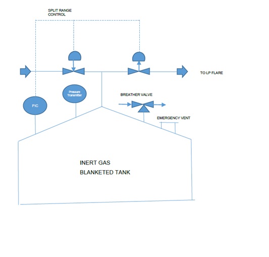
A fixed roof tank storing flammable material is having inert gas blanketing. The outlet of nitrogen blanket is taken to a LP flare system. Below is the sequence of pressure set point engineering (refer figure 7.37 below also):
- First, calculate the inbreathing and outbreathing flow rates based on API 2000.
- Next based on the flowrate of out-breathing to LP flare and the back pressure of flare, calculate the pressure drop in the flare header, to arrive at the pressure required at outlet of out-breathing control valve. Let us say the friction drop in LP header is 150 mm WC (mm water column), & pressure at valve outlet is 400 mm WCg.
- Next step is to provide certain pressure drop across the out breathing control valve. This pressure drop should be at least 1/3rd of friction drop in outlet line to flare, for good controllability. In this example, we provide 50 mm WC across valve.
- Once the inlet pressure to out breathing control valve is established, this is the top setpoint of pressure in the tank pressure controlling range. In example thus, top operating pressure is 450 mm WCg. At this point, the control valve is fully open.
- The high pressure alarm on tank needs to be set above this pressure of point (4). Thus, high pressure alarm will be 500 mm WCg.
- The breather valve positive pressure will be above the high pressure alarm setpoint. Thus, this will be 550 mm WCg. Note that breather valve will have 10% accumulation, thus, it will be fully open at 605 mm WCg.
- The emergency vent valve setpoint will accordingly be above the breather valve positive set pressure. The setpoint of emergency valve is also the design pressure of tank on positive side. In our example, emergency valve will be set at 650 mm WCg. This is also the design pressure of tank. One can however keep design pressure little above emergency valve set point also. Both are acceptable.
- Now, one needs to provide an operating range for tank operation. Thus, the outbreathing control valve will be fully closed at 350 mm WCg inlet pressure.
- There is a dead band normally provided between the closing of inlet control valve and opening of outlet control valve. In our example, this will be between 200 mm WCg and 350 mm WCg.
- Thus, inlet control valve will start to open at 200 mm WCg. It will be fully open at 100 mm WCg.
- Still if pressure in tank drops, the low pressure alarm will come in at 50 mm WCg.
- The inbreathing set point of PVRV will be set at (-22 mm WCg) and with 10% accumulation it will be full open at (-25 mm WCg).
- Thus tank design pressure can be set at (-25 mm WCg).
In summary, tank design pressure is (-25) / 650 mm WCg.
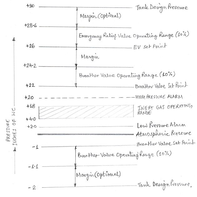
Fig 7.37: the typical setting of tank pressures
The above diagram shows establishing of key pressures for an atmospheric storage tank. The Pressure/Vacuum (PV) Valve is really two valves in one. One is for pressure, and the other is for vacuum. The principle of operation is the same. As the pressure on the pressure side of a PV valve rises, the force due to pressure reduces the seating force of the pallet and it starts to leak. Leakage, however, is relatively insignificant until the set point is reached, at which point the flow increases dramatically and follows the flow curves given by the manufacturer. Beyond the set point, PV valves do not “pop” open, but slowly lift as the overpressure (the actual upstream pressure above the value of the setpoint) increases.
A narrow operating pressure range becomes particularly more important for systems that have inert gas blanketing or large tanks with shallow roof angles that have a very low failure pressure. The problems with sufficient margins to allow vents to operate within the design pressure of the tank become more acute for large diameter tanks. Smaller tanks can frequently take the higher pressures without the need for special design consideration, whereas large tanks will be damaged if the internal pressure exceeds the design pressure.
Emergency vent valves are simply large PV valves capable of venting greater than normal venting loads caused by emergency conditions.
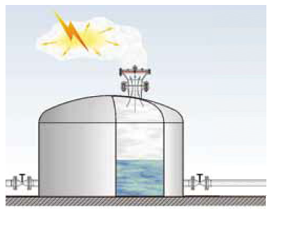
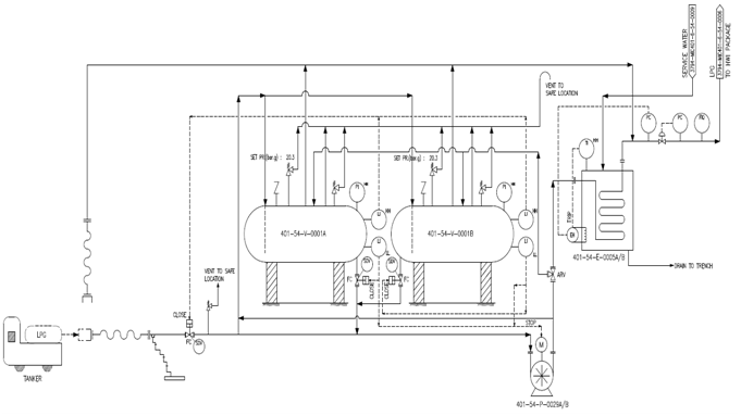
Fig 7.38: Typical Inert Gas Blanketed Tank with a vent to flare
7.4.13 Process Datasheet Preparation:
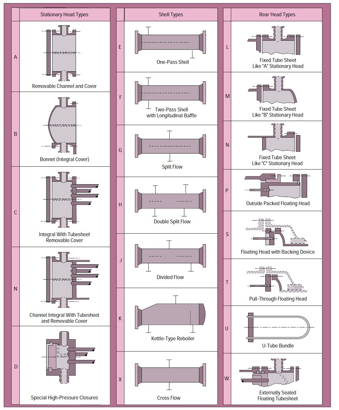
i) Choosing Tank / Storage Vessel Type
Operation at above 18 kPag (2.5 psig) should preferably consider a bullet (a horizontal pressure vessel with L:D ratio that may exceed 5:1).
In some applications, provision of a spheroid or sphere will prove more economic than use of multiple bullets.
Note: Tanks handling liquids with solids contamination require special attention.
ii) Optimizing Vessel Size
The following guidelines should be followed in optimizing dimensions:
a) Tanks:
As a general rule, storage tanks should be limited to a maximum height of 25 m (80 ft) and 60 m (200 ft) diameter.
As a general rule, the cheapest tank will have a height: diameter ratio of 1, although standard tank dimensions should be used wherever shop built tanks are used as this will help reduce cost.
b) Drums / Bullets:
Normal Length / Diameter (L/D) ratio is 2:1 to 5:1 for horizontal bullets with > 3:1 often being the most economic in low-pressure applications. As pressure increases, the economic L/D tends to increase. The higher range of L/D’s is advantageous for horizontal separators and settlers. Also, refer to chapter 9 on “Separators” for more information on L/D.
Minimum drum size should be 610 mm (24”) inside diameter (ID). Small drums can sometimes be fabricated more economically using 24 or 30” outside diameter pipe.
Start by specifying inside diameters and T/T lengths in 152 mm (6”) increments. The Mechanical Engineer responsible for the design of the vessels may come back to Process if a more economical design is possible. This could occur where using standard plate sizes in 610 mm (2 ft) increments are a better fit, or in very high pressure and/or alloy services they may suggest tighter dimensions down to 75 mm (3”) or even 25 mm (1”) increments in order to reduce cost. The Process Engineer should adjust the elevations on the vessel sketch he has provided, once overall dimensions are finalized, with all levels referenced to the bottom of the shell.
Table 7.9 provides nominal standard capacities of vertical Steel cylindrical Storage tanks in m3
iii) Nozzle Sizing and Location
It is not possible for Process Engineering to definitively locate all major nozzles. This is due to the uncertainty of vessel reinforcement pad sizes and other mechanical details. However, Process Engineering must indicate the number, size, and general location of
Mihir’s Handbook at just USD 2.0/ebook (India: Rs.150/ebook)