16.2.2 Liquid Fuel
16.2.2.1 Introduction
Fuel oil is a fraction obtained from petroleum distillation, either as a distillate or a residue. Broadly speaking, fuel oil is any liquid petroleum product that is burned in a furnace or boiler for the generation of heat or used in an engine for the generation of power. In this sense, heavy fuel oil (HFO) or diesel are types of fuel oil. Fuel oil is made of long hydrocarbon chains, particularly alkanes, cycloalkanes and aromatics. The term fuel oil is also used in a stricter sense to refer only to the heaviest commercial fuel that can be obtained from crude oil, heavier than gasoline and naphtha.
Fuel oil systems are provided to ensure a constant regulated supply of oil to burners of steam boilers and process furnaces. The system includes a fuel oil pump and heater set which discharges oil at a constant pressure and at the required condition of temperature and viscosity so that atomisation and efficient combustion are possible.
Dependent on the grade of Fuel oil and process demand, the source may be from process make within the complex, subsidized by import to meet the total complex demand or imported via road, rail or marine off-loading facilities.
Where gas is available for fuel and there is a preference for it, Fuel oil make may be exported via road, rail or marine off-loading facilities.
A typical analysis of a fuel oil or waste liquid contains the following information:
- Ultimate analysis: The results indicate the quantities of sulfur, hydrogen, carbon, nitrogen, oxygen and ash.
- API gravity
- Heating value
- Viscosity
- Pour point: The pour point is the lowest temperature at which a liquid fuel flows under standardized conditions.
- Flash point: The flash point is the temperature to which a liquid must be heated to produce vapours that flash but do not burn continuously when ignited.
- Water and sediment: The water and sediment level, also called bottom sediment and water (BSW), is a measure of the contaminants in a liquid fuel. The sediment normally consists of calcium, sodium, magnesium and iron compounds. For heavy fuels, the sediment may also contain carbon.
Additional information, which is often required when designing a boiler, includes:
- Carbon residue,
- Asphaltenes,
- Elemental ash analysis,
- Burning profile, and
- Distillation curve.
Refer table 16.2.3 below for fuel oil analysis for commercial grades.
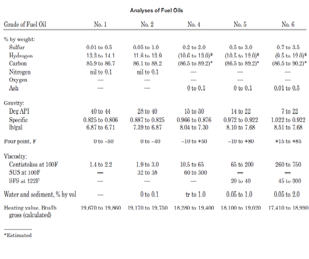
Table 16.2.3: Analysis of commercial fuel oil grades
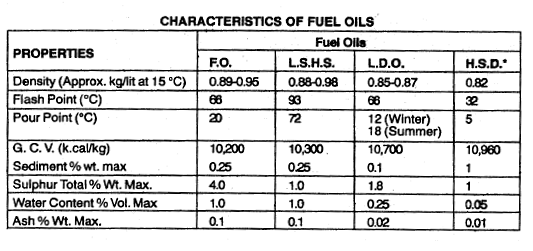
Table 16.2.4: Typical characteristics of various liquid fuel types
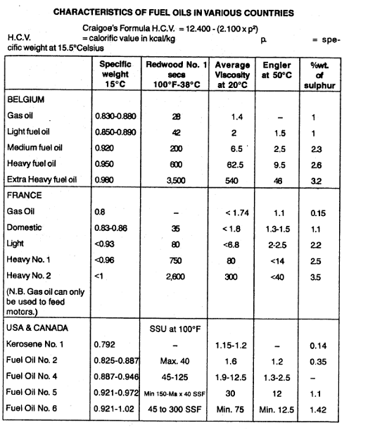
Table 16.2.5: Comparison of properties of fuel oil amongst various countries
16.3 Compressed Air system
Compressed air is supplied on industrial sites for two main purposes, as Instrument Air for control systems and Plant Air for general use.
Instrument Air systems provide a constant flow of dry compressed air at the pertinent conditions to maintain the following services:
Instrumentation (control valves, positioners, shut down valves)
Process Air
Plant Air is supplied for the following services:
Service Air (utility stations)
Motive Air (to run air motor driven equipment e.g. air operated double diaphragm pumps (AODD))
Maintenance facilities (purging equipment containing chemical vapour/inert gas to allow man entry)
Cleaning air (soot blowers, workshops)
16.3.1.1 Determination of System Capacity
(i) Capacity of Instrument Air System
The capacity of the system is to be based upon the total requirements of all connected loads, assuming all instruments operate simultaneously at maximum air consumption. The capacity of the Instrument Air system cannot be accurately assessed until the process control diagrams are complete and a provisional count of the instrumentation is possible.
When accurate manufacturer’s data is not available, the following assumptions are acceptable in calculating the Instrument Air requirements, based on all instrument operating simultaneously:
| Users | Instrument Air Rate per single (1) Device | |
| [Nm3/h] | [scfm] | |
| Old type control valve with fully pneumatic system (includes leakage rate of app. 0.3 Nm3/h) | 2.98 | 1.75 |
| Modern type control valve, electronically controlled with only the actuator using Instrument Air (includes leakage rate of app. 0.3 Nm3/h) | 1.50 | 0.88 |
| On-Off Isolation Valve (includes leakage rate of app. 0.3 Nm3/h) – only fraction of on-off valves needs to be considered operating simultaneously for normal consumption, say 10% | 5.53 | 3.25 |
| Analyzer (oxygen, chromatograph) | 8.50 | 5 |
| Analyzer (moisture, pH, conductivity, water, emission) | 3.40 | 2 |
| Louvers / Dampers | 8.50 | 5 |
| Miscellaneous (compressor pulse jet, on-line / off-line washing, dry gas seal panel, anti surge valve etc.) | As required | As required |
| Margin to be added | % | |
| Margin for air dryer regeneration losses during operation (this depends on vendor design for air dryers) | + 10% to 25% | |
| Margin to avoid overloading the compressor | + 15% to 20% | |
| Margin for leakage in the system (optional- see note 1) | + 10% | |
Note 1: In case GI pipes are used for instrument air as is usual practice, then connectors are union joints since GI pipes cannot be welded. Here, this margin is appropriate. However, if instrument air piping is SS 304 with flanges, then this margin can be ignored)
Table 16.3.1: Recommended Typical Instrument Air Requirements
(ii) Capacity of Plant Air System
Plant Air demand is difficult to predict as invariably plant modification and new constructions services are to be considered in addition to normal plant operations: Service Air, Furnace Decoking and maintenance workshop demands. The largest demand for Plant Air in a production plant is for furnace steam / air decoking (normally 2,500 NM3/hr), which may vary considerably with the type of plant size and number of furnaces.
| User | Plant Air Rate [Nm3/h] |
| Production Plant | As required in consultation with licensor / vendors |
| Plant Service Air (one utility stations at 85 Nm3/h each) | 85 |
| Maintenance workshop | 100 maximum |
Table 16.3.2 Typical Plant Air Requirements
Note that, sometimes, decoke air has its own compressor and in such cases the consumption would not be considered part of Plant Air.
Table 16.3.3 shows demands and operating conditions for pneumatic tools and construction equipment. Note that these are peak values and that average loads are often 10-35% of the peak values quoted.
| Tool | Weight [kg] | Air Rate [lts/min] | Work. Pres. [barg] |
| Clay diggers | 11 | 800 | 4.9 |
| Clay diggers | 14 | 600 to 680 | 4.9 |
| Clay diggers | 15.5 | 680 | 4.9 |
| Clay diggers | 18 | 1600 | 4.9 |
| Concrete tampers | 18 | 1100 | 4.9 |
| Riveting Hammer Light | 1.6 to 1.8 | 200 to 250 | 4.9 |
| Riveting Hammer Heavy | 7.2 to 11.4 | 88 to 900 | 4.9 |
| Drilling Machines (1/8”-3/4”) | 0.75 to 3.9 | 400 to 800 | 4.9 to 5.9 |
| Drilling Machines (7/8”-1 1/4”) | 6.3 to 14 | 1000 to 1600 | 4.9 to 5.9 |
| Drilling Machines (2”) | 22 | 2500 | 4.9 to 5.9 |
| Hand Grinder (5/16” dia.) | 0.5 to 1.0 | 400 to 650 | 4.9 |
| Hand Grinder (4”x2”-6”x1 1/4″) | 4.8 to 5.1 | 1000 | 4.9 |
| Hand Grinder (8”x1 1/2″) | 7.5 | 1500 | 4.9 |
| Grinders with Flexible Pad (8”-10” dia.) | 5.5 | 1900 | 4.9 |
Table 16.3.3: Approximate peak Demands for Pneumatic Tools
Dryers
The most common measurement of compressed air water content is dew point. Dew point is the temperature where air is saturated with water and moisture will begin to condense. In other words, it’s the point where dew begins to form. Dew point is always stated as a temperature. Simply put, dew point is the temperature where condensation begins.
In compressed air applications, pressure is critical when discussing dew point. Compression and expansion of air affects its dew point. Generally speaking, compression increases dew point, and expansion (i.e. de-compression) lowers dew point.
For this reason, the phrase “pressure dew point (PDP)” is commonly used. This term usually refers to the dew point of the compressed air at full line pressure. Conversely the phrase “atmospheric dew point” refers to what the dew point would be if fully depressurized to atmospheric conditions.
Fig 16.3.1 provides conversion chart of pressure to atmospheric dew point for compressed air at various pressures. To obtain the dew point temperature expected if the gas were expanded to a lower pressure proceed as follows:
- Using “dew point at pressure” locate this temperature on scale at right hand side of chart.
- Read horizontally to intersection of curve corresponding to the operating pressure at which the gas was dried.
- From that point read vertically downward to curve corresponding to the expanded lower pressure.
- From that point read horizontally to scale on right hand side of chart to obtain dew point temperature at the expanded lower pressure.
- If dew point temperatures of atmospheric pressure are desired, after step (ii) above, read vertically downward to scale at bottom of chart, which will provide “Dew Point at Atmospheric Pressure”.

Fig 16.3.1: Pressure dewpoint versus atmospheric dewpoint conversion
Two 100% air dryer packages are normally installed (duty and stand by).
Dryer types and details of each are provided below:
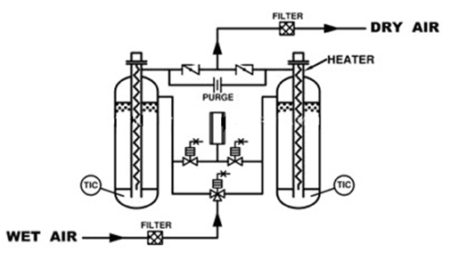
Compressed Air Dryers are mainly used in industries for various applications in pneumatic tools, pneumatic instruments and pneumatic machines and in a variety of production processes. The consequences of using wet air are rust and scale deposits in steel pipes, increased resistance in flow, malfunctioning of process control instruments, corrosion and damage to electromagnetic valves and pneumatic system, peeling and blistering effect on spray painted surface, etc. Thus it will affect the quality of product and lead to excessive maintenance cost.
The sketch below shows a typical Compressed air system to remove these damaging impurities and get Clean and Dry air. When compressed to 7 Kg/cm2g, the temperature of discharge air reaches around 140oC. The after cooler and Separator installed after the compressor will cool the air, and remove @90% of moisture and oil. For instance, when the compressor takes in 100 NM3/h of ambient air at 40oC and 50% relative humidity, at 7 Kg/cm2g, the after cooler will condense an average of 30 liters of water in 24 hours. If the outlet air temperature from the after cooler is 40oC, it still contains 8000 ppm moisture. At 45oC, compressed air contains 10,500 ppm, at 50oC, 13,500 ppm moisture which is removed by Air Dryer. Therefore, lower the temperature of air at dryer inlet, smaller would be the size of Air Drying Unit.
Dryer types are as below:
- Internally Heat Reactivated Type Air Dryers
- Blower Reactivated Type Air Dryer
- Heatless Type Air Dryers
- Heat of Compression Type Air Dryers
- Refrigerated Type Air Dryers
- No Purge Loss Type Air Dryers
(a) Internally Heat Reactivated Type Air Dryers
Internally heat reactivated type Air Dryers (fig 16.3.2) are used when one needs compressed air of very low Dew point of (-) 60oC or (-) 80oC. In this design, the desiccant is regenerated at higher temperature, along with small quantity of Dry air purge. Due to purging with Dry air and thermal regeneration, residual moisture loading on desiccant becomes low and this gives very low Dew point. The Drying unit has 2-vessels filled with Activated Alumina or Molecular sieves desiccant. One vessel remains in drying cycle for 4 hours, while other vessel is simultaneously regenerated at atmospheric pressure. Around 3% flow of dryer capacity is used as purge for regeneration.
Electrical heaters are provided in a central finned Stainless steel pipe in both drying vessels. Heating cycle is for @ 2 hours and in this time hot purge air increases desiccant temperature to around 100oC. At this temperature regeneration is complete (due to dry air purge). Dew point achieved is @ (-) 40oC.
If still lower Dew point is required, air purging rate is slightly increased to 5% for (-) 60oC and to 7.5% for (-) 80oC Dew point. A Pre-filter with automatic drain valve is provided to remove any physical moisture from compressed air before entering Air dryer. An after filter is also provided in the Dryer outlet to arrest any desiccant dust particles, up to 1 micron size.
Fig 16.3.2: Internally Heat Reactivated Type Air Dryer
Salient Features:
- Longer life of operation
- Requires less attention of operator
- Once installed can be operated automatically
- Heaters and valves are operated automatically
- Internal heaters provide max efficiency resulting in lower power requirement.
- Easy maintenance
| Air Capacity | 5 to 3000 NM3/ Hr |
| Atmospheric Dew Point | (-)40oC to (-)80oC |
| Operating Pressure | 2 to 50 kg/ cm2g |
Table 16.3.6: Details of Internally Heat Reactivated Type Air Dryers
16.5.9 Specification of Boilers
(i) Preferred Arrangement
Required total capacity should be provided by use of at least 3 boilers, but all boilers should be considered to be operating at partial load to supply normal steam requirements. The above is recommended for redundancy purposes only.
All boilers should preferably be considered to be water tube type except small package units of low pressure which may be of fire tube construction.
Boilers should be of the outdoor installation type except that semi outdoor type should be used in cold climates.
Package boilers should be preferred in standard sizes and pressure ranges where commonly available.
Boilers should usually be equipped with automatic fuel burners, forced or induced draft fans, flue gas ducts, soot blowers, platforms and ladders, and other related auxiliaries and accessories, as neccessary. Controls and instruments are usually supplied to a certain degree with the boiler.
(ii) Boilers
The boiler specification should cover all aspects of the expected operating cycle of the boiler. It is important that any special operating aspects such as daily start-up or rapid load swings are covered in the specification of the boiler, which should include the following:
- Analysis of the fuels to be used
- Duty required (maximum and minimum flows, pressure and temperatures and allowable variation)
- Water analysis and expected ranges and feed water temperature
- Layout constraints and access problems
- Any unusual site features such as earthquake or wind problems
- Applicable emissions regulations
- Codes and standards required for the country, plus site safety rules
- Delivery and commissioning requirements
- Auxiliary equipment required and types of drive
- Control system and data management needs
- Guarantees and warranties
- Any essential bid comparison basis such as utility values, capital charges, etc.
(a) Boiler Specifications and a few important terminologies:
Boilers are always typically specified by the following Industrial Boiler Specification Factors.
(Note: At the end of this section are provided guidelines for process engineer to prepare specifications and evaluate vendor bids. Vol II Chapter 30 also provides technical bid evaluation for boilers).
- Steam pressure
- Steam temperature and control range
- Steam flow: Peak, Minimum, Load patterns
- Feed water temperature and quality
- Standby capacity and number of units
- Fuels and their properties
- Ash properties
- Firing method preferences
- Environmental emission limitations: sulfur dioxide (SO2), nitrogen oxides (NOx), particulate, other compounds
- Site space and access limitations
- Auxiliaries
- Operator requirements
- Evaluation basis
Out of these, the usual four most important attributes are:
- Steam flow or evaporation
- Steam outlet pressure (SOP)
- Steam outlet temperature (SOT)
- Feed water (FW) inlet temperature
(b) Steam Flow or Evaporation or Boiler Output
This is the amount of steam generated from the FW supplied at a certain temperature. It is the capacity or the rating of the boiler expressed in pounds per hour (lb/h), kilograms per hour (kg/h), or kilograms per second (kg/s). In a re-heater (RH) boiler, heat is added to steam to raise its temperature from inlet to outlet condition. This also forms a part of evaporation. As the feed temperature varies a good deal and reheating is invariably present in utility boilers, boiler ratings are better designated by the heat duty than evaporation. This is expressed in million British thermal units per hour (MMBtu/h), million kilocalories per hour (MMkcal/h), or megawatt thermals (MWth).
(c) Maximum Continuous Rating
Maximum continuous rating (MCR) is the ability of the boiler to generate and supply the declared amount of steam continuously and effortlessly without any kind of shortfall or side effects (such as overheating or slagging or overloading) on the main boiler or auxiliaries.
(d) Peak Rating
Peak rating is the evaporation that can be sustained by the boiler for a specified period of, for example, 2 or 4 h in a day, to meet an increased need in either the process or the power plant. The concept of peak rating does not apply to HRSGs.
Peak duty is always met at a fractionally reduced efficiency, as the final exit temperature of the gas from the unit would be more than that at an MCR condition (as the fuel flow is higher), leading to higher stack losses.
Usually, the peak duty does not exceed 110% MCR and 4 h in a day, and it is mostly met by making use of the design and test block margins of the boiler and the auxiliaries without having to oversize the equipment.
Mihir’s Handbook at just USD 2.0/ebook (India: Rs.150/ebook)